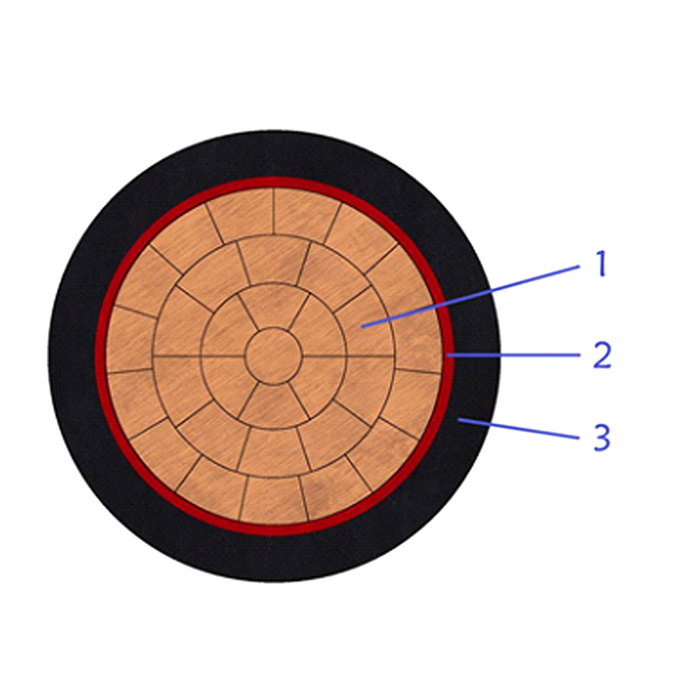
This single-core CU/PVC/PVC cable is designed for low-voltage power transmission......
+ VIEW MOREIndustry News
Content
Selecting the correct Low Voltage (LV) power cable requires satisfying three simultaneous criteria: continuous current carrying capacity, permissible voltage drop limits, and thermal withstand during short circuits. A cable sized solely on load current without accounting for installation method or harmonic distortion will fail prematurely or cause equipment malfunction. For standard commercial installations operating at 400V/230V, the industry benchmark for maximum voltage drop is 3% for lighting circuits and 5% for other power loads from the supply intake to the terminal equipment.
Engineers must prioritize the specific installation environment over generic catalog ratings. A 95mm² XLPE copper cable rated for 280A in free air may only safely carry 195A when installed in a thermally insulated wall or grouped with six other loaded circuits. Compliance with IEC 60364-5-52 or NEC Article 310 mandates applying correction factors for ambient temperature, soil thermal resistivity, and circuit grouping before finalizing the conductor cross-sectional area.
The insulation material dictates the maximum operating temperature, which directly correlates to current capacity and lifespan. While PVC remains common for cost-sensitive residential projects, Cross-Linked Polyethylene (XLPE) offers a 30% higher current rating for the same conductor size due to its superior thermal properties. Understanding these differences prevents oversizing conductors or selecting inadequate materials for high-load industrial applications.
| Parameter | PVC (Polyvinyl Chloride) | XLPE (Cross-Linked PE) | EPR (Ethylene Propylene) |
|---|---|---|---|
| Max Continuous Temp | 70°C | 90°C | 90°C |
| Short Circuit Limit | 160°C (5s) | 250°C (5s) | 250°C (5s) |
| Dielectric Strength | Moderate | High | Very High |
| Typical Application | Residential / Light Commercial | Industrial / Main Feeders | Mining / Heavy Duty Flexible |
When upgrading from PVC to XLPE, engineers can often reduce conductor size by one or two steps while maintaining the same ampacity. For example, a 150mm² PVC cable carries approximately 290A in ground, whereas a 120mm² XLPE cable carries 305A under identical conditions. This reduction offsets the slightly higher unit cost of XLPE insulation through savings in copper weight and easier installation handling.
Excessive voltage drop causes motor overheating, reduced lighting output, and nuisance tripping of sensitive electronics. The calculation must account for both resistance (R) and reactance (X), especially for cables larger than 35mm² where inductive reactance becomes significant. For a balanced three-phase system, the voltage drop formula is:
Consider a 100kW motor load (170A at 0.85 PF) located 120m from the switchboard using 70mm² XLPE copper cable. The manufacturer's impedance data shows R=0.32Ω/km and X=0.082Ω/km at 90°C. The calculated voltage drop is 11.2V (2.8%), which complies with the 5% limit. However, if the starting current is 6× rated (1020A) for 10 seconds, the momentary drop reaches 67V (16.7%). If this exceeds the motor starter's hold-in threshold, upsizing to 95mm² or installing soft-start equipment becomes mandatory despite steady-state compliance.
Catalog current ratings assume specific reference conditions that rarely match real-world installations. Failing to apply derating factors is the most common cause of cable failure in compliant-looking designs. Key variables requiring adjustment include:
Documentation of all applied correction factors is essential for audit trails and future modifications. Design software should explicitly list each factor rather than presenting only the final adjusted ampacity.
LV power cables must survive the thermal stress of fault currents until the protective device clears the fault. The adiabatic equation determines the minimum required cross-section: S ≥ (Isc × √t) / k, where Isc is the prospective fault current, t is the clearing time, and k is the material constant (143 for XLPE copper, 115 for PVC copper).
At a distribution board with 25kA prospective fault current and a 0.1s breaker clearance time, the minimum XLPE copper conductor is S ≥ (25000 × √0.1) / 143 = 55.4mm². Therefore, a 50mm² cable would be thermally damaged despite having adequate continuous current rating; 70mm² is the minimum compliant size regardless of load. This check must be performed at every point in the network where fault levels change, particularly at sub-distribution boards downstream of transformers.
Automatic disconnection times depend on earth fault loop impedance (Zs). For TN systems, Zs must satisfy Zs ≤ U₀ / Ia, where Ia is the current causing automatic operation within the prescribed time. Long cable runs with small earth conductors frequently fail this test even when phase conductors are adequately sized. Using a full-size neutral and earth conductor, or paralleling separate earth cables, ensures reliable protection operation and avoids dangerous touch voltages during faults.

This single-core CU/PVC/PVC cable is designed for low-voltage power transmission......
+ VIEW MORE
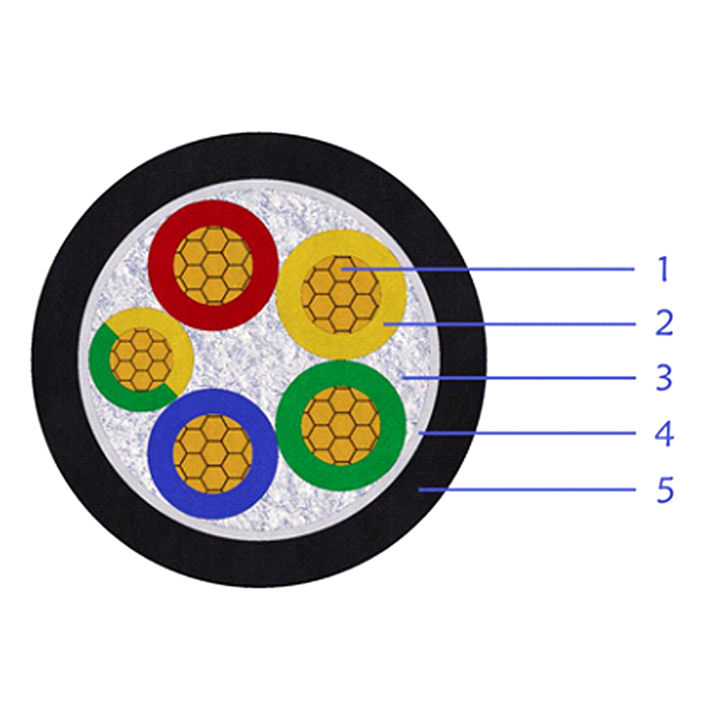
The multi-core CU/PVC/PVC cable is engineered for low-voltage distribution where......
+ VIEW MORE
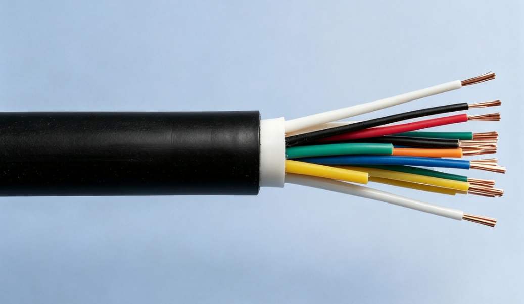
Suitable for transmission of analogue and digital control signals between comput......
+ VIEW MORE
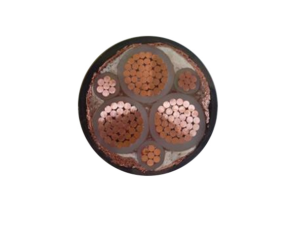
Designed for variable frequency drive systems with rated voltage 0.6/1kV and bel......
+ VIEW MORE
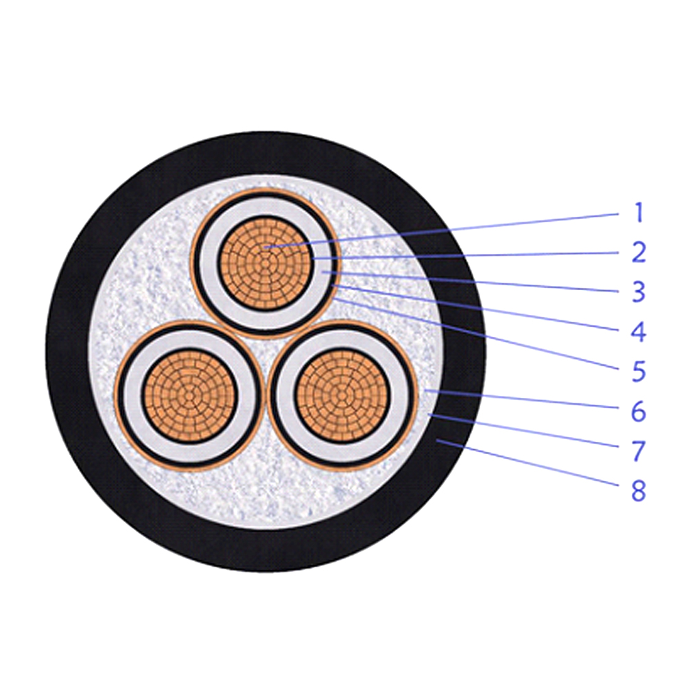
This multi-core XLPE insulated unarmored power cable is designed for medium volt......
+ VIEW MORE
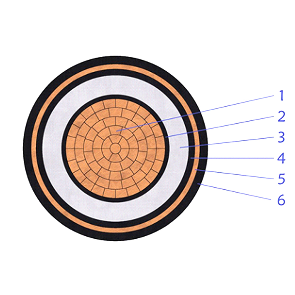
This 18/30(36)kV XLPE insulated unarmored power cable is developed for medium vo......
+ VIEW MORE
Ready To Customise
Your Cable Products?