Home / News / Industry News / MV Power Cables: Sizing, Testing & Installation Standards
New

MV Power Cables: Sizing, Testing & Installation Standards


Critical Design Parameters for Medium Voltage Systems

Successful MV power cable deployment depends on satisfying three non-negotiable engineering constraints: dielectric integrity under continuous and impulse voltage stress, thermal capacity for both steady-state and emergency loading, and mechanical resilience during installation and fault conditions. Unlike low voltage systems where ampacity often governs sizing, medium voltage cables (1kV–36kV) are frequently sized by short-circuit withstand capability or voltage drop limits before current carrying capacity becomes the controlling factor. Industry data indicates that over 60% of MV cable failures originate from improper termination or jointing rather than conductor defects, making accessory compatibility and installation workmanship as critical as cable selection itself.

Engineers must specify cables based on system grounding philosophy and fault duration. A solidly grounded 13.8kV system requires 100% insulation level cables, while resistance-grounded or ungrounded systems experiencing temporary overvoltages demand 133% or 173% insulation levels to prevent dielectric breakdown during single-line-to-ground faults lasting up to one hour. Selecting standard 100% insulation for an ungrounded system is a common design error leading to premature failure within months of energization.

Insulation Technology and Dielectric Performance

Modern MV power cables predominantly use Cross-Linked Polyethylene (XLPE) or Ethylene Propylene Rubber (EPR) insulation, having largely replaced oil-impregnated paper designs. The choice between these polymers affects not only current rating but also diagnostic testing methodology and expected service life. TR-XLPE (Tree-Retardant XLPE) has become the industry standard for underground distribution due to its resistance to water treeing, extending wet-environment service life from 15 years to 30+ years compared to conventional XLPE.

Technical Comparison of MV Cable Insulation Materials
Property Conventional XLPE TR-XLPE EPR
Max Continuous Temp 90°C 90°C 90°C
Emergency Overload 130°C 130°C 130°C
Water Tree Resistance Low High Very High
Dielectric Constant 2.3 2.3 2.8–3.2
Charging Current Lower Lower Higher

Impact of Dielectric Properties on System Design

The higher dielectric constant of EPR results in 20–30% greater charging current compared to XLPE for identical geometry. In long underground runs exceeding 5km, this capacitive current can consume significant ampacity and may require shunt reactors for voltage regulation. Conversely, EPR's superior flexibility and moisture tolerance make it preferable for mining, marine, and frequent-relocation applications despite the electrical trade-offs. TR-XLPE represents the optimal balance for most utility and industrial fixed installations.

Ampacity Derating and Thermal Management

MV cable ampacity tables assume specific reference conditions that rarely match actual field installations. Engineers must apply multiplicative correction factors for ambient temperature, soil thermal resistivity, depth of burial, and circuit grouping per IEEE Std 835 or IEC 60287. A common oversight is neglecting soil thermal resistivity variation; assuming standard 90°C·cm/W when actual site measurements show 150°C·cm/W can result in 25–30% overestimation of safe current capacity, leading to accelerated insulation aging.

  • Duct Bank Configurations: Cables in PVC conduits encased in concrete have significantly reduced heat dissipation versus direct burial. A 3×3 duct bank at 75% load factor may require upsizing two AWG sizes compared to isolated direct-buried cables.
  • Proximity Effect: Single-conductor MV cables in trefoil formation experience mutual heating. Spacing cables one diameter apart reduces ampacity by approximately 12% compared to touching trefoil, but improves fault locating accessibility.
  • Harmonic Loading: Variable frequency drives feeding MV motors generate harmonic currents that increase conductor losses. For THD >15%, apply IEEE 519 derating factors or specify oversized neutrals even on three-phase feeders.
  • Cyclic Rating: Emergency overload capability (typically 130°C for XLPE) is time-limited. IEEE C57.129 provides cyclic rating methods allowing temporary 150% loading for 2 hours following normal operation, useful for contingency planning without permanent oversizing.

Field Testing and Commissioning Protocols

Post-installation testing validates cable integrity and establishes baseline data for future diagnostics. Modern standards strongly discourage DC hipot testing on extruded dielectric MV cables, as DC testing can initiate space charge accumulation that accelerates AC failure within weeks. Instead, AC resonance testing or Very Low Frequency (VLF) with tan delta measurement are the accepted commissioning methods.

Recommended Test Sequence and Acceptance Criteria

  1. Visual & Mechanical Inspection: Verify bending radius compliance (minimum 12× OD for single-core, 8× OD for multi-core), shield continuity, and proper grounding of metallic sheaths at terminations.
  2. Conductor Resistance Test: Measure DC resistance and compare to manufacturer specs corrected to 20°C. Deviations >5% indicate poor splices or damaged conductors.
  3. Insulation Resistance (IR): Apply 5kV DC megohmmeter for 1 minute minimum. Acceptable values exceed 100 MΩ·km for new XLPE cables; trending IR over time is more valuable than absolute readings.
  4. VLF Tan Delta: Measure dielectric loss at 0.1 Hz across multiple voltage steps. New TR-XLPE should exhibit tan δ < 0.001 at rated voltage; values >0.003 suggest water tree degradation or voids requiring investigation.
  5. Partial Discharge (PD): Perform offline PD testing at 1.7U₀ for acceptance. Background noise must be characterized first; genuine PD activity >10 pC at test voltage warrants rejection regardless of passing other tests.

Documentation of all test results with environmental conditions creates essential asset history. Digital records linked to GIS coordinates enable predictive maintenance programs that reduce unplanned outages by 40–60% according to EPRI reliability studies.

Termination and Jointing Best Practices

MV cable accessories represent the highest-risk components in any medium voltage installation. Failure statistics consistently show that termination defects account for 3–5× more outages than cable body failures. Key principles for reliable accessory performance include strict adherence to manufacturer installation instructions, environmental control during assembly, and verification of stress cone positioning.

Stress control is paramount at cut-back points where electric field concentration occurs. Premolded slip-on terminations rely on precise dimensional tolerances; stretching or misaligning the stress cone by even 5mm can create localized field enhancement exceeding design limits. Cold-shrink technologies offer more forgiving installation windows but require verification of complete shrinkage and absence of air gaps. Heat-shrink kits demand controlled flame application; overheating degrades semiconductive layers while insufficient heat leaves interfacial voids prone to partial discharge.

Environmental protection during installation cannot be overstated. Moisture ingress during rainy or high-humidity conditions compromises interface integrity. Temporary shelters with dehumidification are mandatory when relative humidity exceeds 80% or when surface condensation is possible. Post-installation sealing of conduit entries and termination housings prevents long-term moisture migration that manifests as failures years after commissioning.

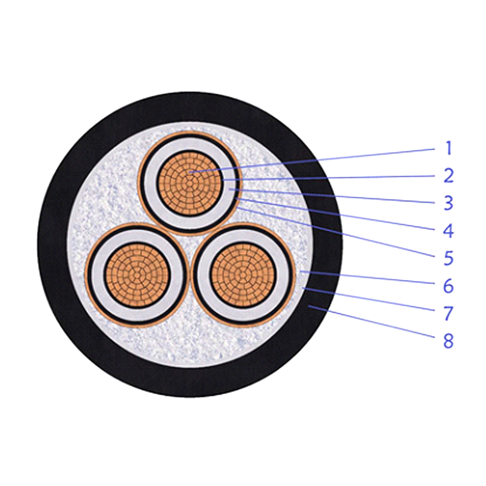
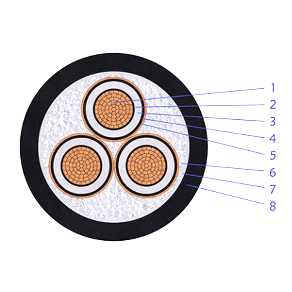
Multi-Core XLPE Insulated Copper Tape Screen Double Steel Tape Armored Power Cable