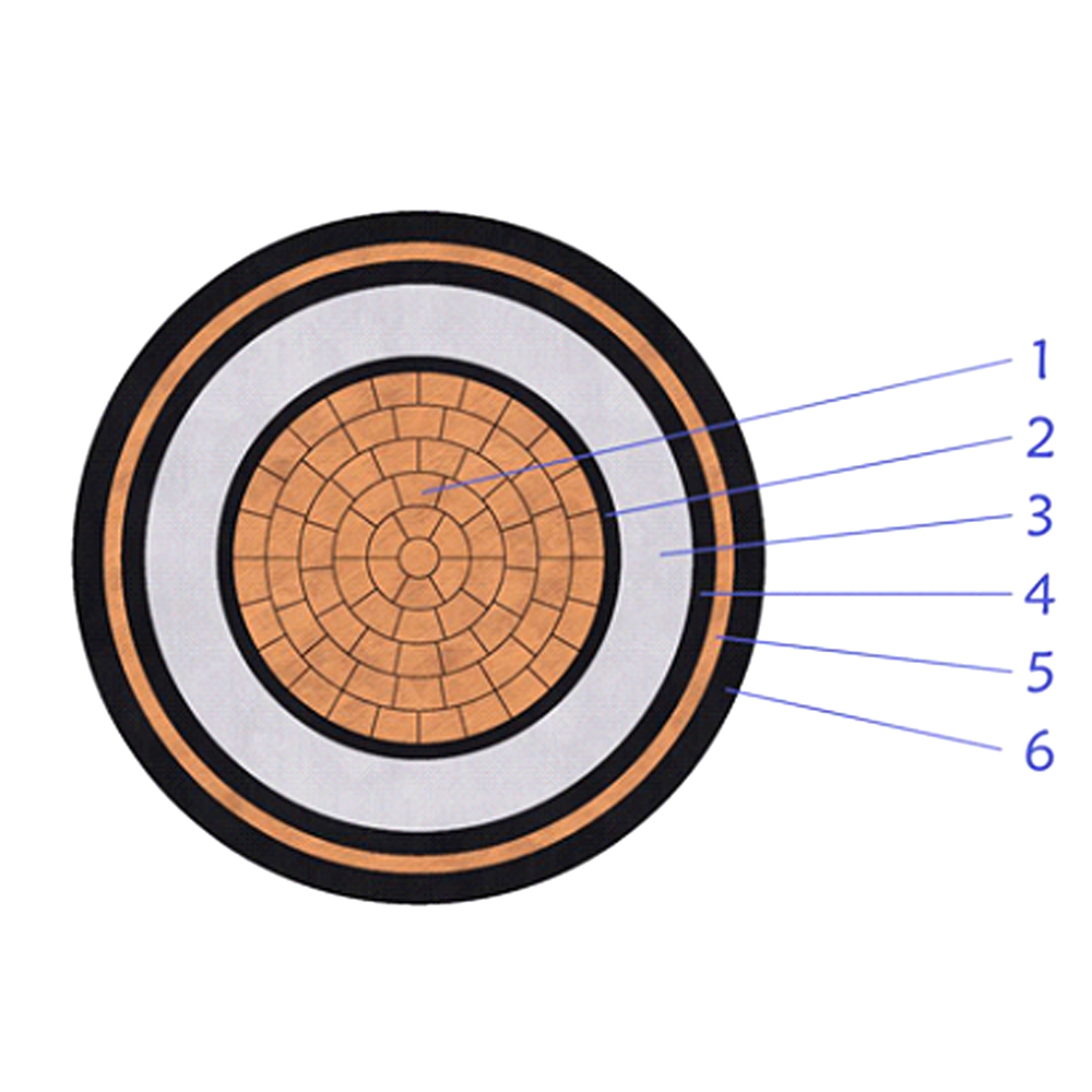
This 3.6/6(7.2)kV medium voltage unarmored power cable is designed for fixed ins......
+ VIEW MOREIndustry News
Content
Cross-linked polyethylene (XLPE) insulated power cables are widely used in utility distribution networks, industrial facilities, renewable energy projects, and modern infrastructure.
XLPE insulation offers a higher permissible continuous conductor temperature and lower dielectric losses than conventional PVC insulation. These characteristics make XLPE an established insulation material for low- and medium-voltage power distribution.
However, insulation material alone does not determine cable performance. Proper cable selection must also consider conductor size, voltage rating, installation conditions, short-circuit requirements, environmental exposure, and applicable technical standards.
This article explains the technical characteristics of XLPE-insulated power cables, their typical applications, and the key engineering considerations for project specification.
XLPE and PVC are both widely used insulation materials in power cable manufacturing.
Their electrical and thermal characteristics differ, making each suitable for different applications.
| Parameter | Conventional PVC Insulation | XLPE Insulation |
|---|---|---|
| Material type | Thermoplastic | Cross-linked thermosetting polymer |
| Typical maximum continuous conductor temperature | 70°C | 90°C |
| Typical maximum short-circuit conductor temperature | 160°C | 250°C |
| Dielectric constant | Generally higher | Generally lower |
| Dielectric loss factor | Generally higher | Generally lower |
| Dimensional stability at elevated temperatures | Limited by thermoplastic softening | Improved resistance to thermal deformation |
| Common applications | LV building wiring and general power distribution | LV and MV power distribution, industrial facilities, infrastructure, renewable energy |
Engineering note: The temperature values shown are typical ratings for common power cable insulation systems. Actual permissible temperatures must be verified against the applicable product standard and manufacturer's published data.
Under comparable installation conditions, XLPE's higher permissible operating temperature may allow a higher continuous current rating than conventional 70°C PVC insulation.
However, the exact difference depends on cable construction, conductor material, installation method, and thermal conditions.
XLPE does not provide a universal percentage increase in ampacity.
Conventional PVC-insulated power cables are commonly designed for a maximum continuous conductor temperature of 70°C.
XLPE-insulated power cables are commonly designed for a maximum continuous conductor temperature of 90°C.
This higher permissible temperature can provide additional thermal design flexibility in applications such as:
Industrial power distribution.
Utility distribution networks.
Underground cable installations.
Renewable energy collection systems.
Commercial and infrastructure projects.
Under suitable installation conditions, an XLPE-insulated cable may carry more current than a comparable cable using conventional 70°C PVC insulation.
However, conductor sizing must satisfy three separate engineering requirements:
Continuous current-carrying capacity.
Voltage drop limitation.
Short-circuit thermal withstand.
Higher permissible conductor temperature does not automatically allow longer cable runs or lower electrical losses.
Conductor resistance increases with operating temperature, and voltage drop must be evaluated independently.
XLPE generally has a lower dielectric constant and dielectric dissipation factor than conventional PVC insulation.
These characteristics can reduce dielectric losses in suitable cable designs, particularly where operating voltage and cable length make insulation losses relevant.
However, dielectric losses and conductor losses are different components of total cable losses.
Conductor losses depend primarily on current, conductor resistance, operating temperature, and the electrical characteristics of the circuit.
XLPE insulation should therefore not be described as automatically reducing total electrical losses under all operating conditions.
The overall loss performance of a cable system should be evaluated according to the selected cable construction and actual operating conditions.
XLPE is produced through a cross-linking process that changes the molecular structure of polyethylene.
Compared with conventional thermoplastic PVC, XLPE provides improved dimensional stability at elevated temperatures.
This characteristic supports its use in power cables designed for higher permissible operating temperatures.
However, XLPE insulation remains subject to defined thermal limits.
Exceeding the specified continuous operating temperature or permissible short-circuit temperature may accelerate insulation ageing or cause damage.
Emergency loading and short-circuit performance must therefore be evaluated according to the applicable standard and cable manufacturer's technical data.
XLPE-insulated power cables are widely used in underground distribution networks, industrial facilities, renewable energy projects, and infrastructure installations.
Depending on the application, additional construction features may include:
Metallic screens for medium-voltage cables.
Steel wire armour (SWA).
Steel tape armour (STA).
Aluminium wire armour (AWA).
Longitudinal water-blocking components.
Radial moisture barriers, where specified.
PVC, PE, or low-smoke zero-halogen outer sheaths.
These features serve different engineering purposes and should be specified according to the installation environment.
XLPE insulation alone does not make a cable waterproof, flame-retardant, fire-resistant, or suitable for every outdoor application.
XLPE power cable design, manufacturing, testing, and installation should reference the applicable edition of the relevant international standards.
| Standard | Primary Scope |
|---|---|
| IEC 60228 | Conductors of insulated cables, including conductor classes and electrical resistance requirements |
| IEC 60502-1 | Power cables with extruded insulation for rated voltages of 1 kV (Um = 1.2 kV) and 3 kV (Um = 3.6 kV) |
| IEC 60502-2 | Power cables with extruded insulation for rated voltages from 6 kV (Um = 7.2 kV) up to 30 kV (Um = 36 kV) |
| IEC 60287 | Calculation of cable current ratings under specified operating and installation conditions |
| IEC 60853 | Calculation of cyclic and emergency current ratings of cables |
| IEC 60332 | Specified flame propagation tests for electric cables |
| IEC 60754 | Tests on gases evolved during combustion of cable materials |
| IEC 61034 | Measurement of smoke density of cables burning under defined conditions |
The applicable standard should be selected according to cable voltage rating, construction, intended application, and project requirements.
Compliance with one standard does not automatically establish compliance with all other standards listed above.
For example, a power cable manufactured according to IEC 60502-1 is not automatically qualified as a flame-retardant, fire-resistant, or low-smoke zero-halogen cable.
Additional construction requirements and relevant test documentation may be necessary.
Low-voltage XLPE-insulated power cables are widely used in:
Industrial power distribution.
Commercial building mains.
Utility distribution systems.
Infrastructure projects.
Renewable energy facilities.
Common cable constructions include:
Copper conductor / XLPE insulation / PVC sheath.
Aluminium conductor / XLPE insulation / PVC sheath.
Copper conductor / XLPE insulation / PE sheath.
XLPE-insulated armoured power cables.
XLPE-insulated cables with specified low-smoke zero-halogen sheaths.
A commonly used rated voltage is 0.6/1 kV.
The final cable construction should be selected according to the applicable product standard, installation conditions, and project specification.
Medium-voltage XLPE-insulated power cables are commonly used for:
Utility distribution networks.
Industrial plant feeders.
Solar farm collection systems.
Onshore wind farm collection systems.
Infrastructure power distribution.
Data centre primary distribution.
Common rated voltage designations include:
| Rated Voltage U₀/U | Maximum System Voltage Um |
|---|---|
| 3.6/6 kV | 7.2 kV |
| 6/10 kV | 12 kV |
| 8.7/15 kV | 17.5 kV |
| 12/20 kV | 24 kV |
| 18/30 kV | 36 kV |
The applicable voltage designation must be confirmed against the relevant product standard and project specification.
Medium-voltage cable constructions may include:
Copper or aluminium conductors.
Conductor screens.
XLPE insulation.
Insulation screens.
Metallic screens.
Inner coverings, where applicable.
Metallic armour, where specified.
Suitable outer protective sheaths.
Single-core and multicore configurations are available depending on the cable design and application.
For single-core AC cables, non-magnetic armour such as aluminium wire armour is commonly selected where armour is required.
Armour selection should account for mechanical requirements, magnetic losses, cable arrangement, and installation conditions.
Renewable energy projects require cables suitable for different electrical systems and installation environments.
The cable used between photovoltaic modules is not necessarily the same type used for low-voltage AC distribution or medium-voltage collection.
| Application | Typical Electrical System | Cable Selection |
|---|---|---|
| PV modules and DC strings | Project-specific DC voltage, commonly up to 1,500 V DC | Dedicated photovoltaic cable meeting applicable requirements such as IEC 62930 or EN 50618 |
| Inverter AC output | Project-specific LV AC voltage | Suitable LV XLPE power cable |
| Solar farm MV collection | Project-specific MV distribution voltage | MV XLPE power cable |
| Substation connection | According to the project distribution design | Appropriately rated power cable |
Dedicated photovoltaic cables must be selected according to their DC voltage rating, environmental performance, and applicable product standard.
A conventional XLPE power cable should not automatically be treated as a substitute for a dedicated photovoltaic cable.
XLPE-insulated power cables are commonly used in onshore wind farm collection and distribution systems.
The required cable construction depends on:
Rated voltage.
Conductor cross-sectional area.
Installation method.
Soil and ambient temperature.
Mechanical protection requirements.
Moisture exposure.
Project-specific fire performance requirements.
Cables installed inside wind turbines may require additional flexibility, torsion resistance, or other specialized characteristics.
These requirements should be specified separately from conventional fixed-installation XLPE power cables.
Battery energy storage systems may require different cable types for DC battery circuits, low-voltage AC distribution, and medium-voltage connections.
Cable selection should consider:
AC or DC application.
Rated operating voltage.
Continuous current.
Short-circuit requirements.
Installation temperature.
Cable routing and mechanical protection.
Applicable fire performance requirements.
The suitability of a cable for a particular BESS application must be verified against its rated voltage, construction, and relevant technical specification.
Although XLPE provides useful electrical and thermal characteristics, it is not a universal solution for every installation.
Standard XLPE insulation does not automatically provide the flame propagation, circuit integrity, or smoke emission performance required for every project.
Depending on the installation, additional requirements may include:
Flame-retardant construction.
Fire-resistant construction.
Low-smoke zero-halogen materials.
Specific flame propagation test performance.
Defined circuit integrity requirements.
Flame retardance and fire resistance are different performance characteristics.
The required cable construction and supporting test documentation should be identified in the project specification.
For outdoor installations, the cable's outer sheath must be suitable for the expected environmental exposure.
UV resistance depends on sheath material, formulation, and relevant performance requirements.
A suitably formulated black PE sheath is commonly used in outdoor cable applications, but colour alone does not establish compliance with a particular UV-resistance requirement.
The suitability of the selected sheath should be verified against the project specification and manufacturer's technical data.
For medium-voltage XLPE cables, prolonged moisture exposure under electrical stress can contribute to water tree formation under susceptible conditions.
Depending on the installation and project requirements, suitable design measures may include:
Water-tree-retardant XLPE insulation.
Longitudinal water-blocking components.
Radial moisture barriers.
Suitable outer sheath construction.
Appropriate cable joints and terminations.
The required water protection should be specified according to the installation environment.
XLPE insulation alone should not be treated as a complete water-blocking system.
Cable joints and terminations are critical components of medium-voltage cable systems.
Improper cable preparation, contamination, moisture ingress, and incorrect accessory installation may compromise system reliability.
Suitable accessories should be selected according to:
Cable voltage rating.
Conductor size.
Insulation diameter.
Cable screen construction.
Installation environment.
Applicable accessory qualification requirements.
Installation should be performed by trained personnel following the accessory manufacturer's instructions.
The economic comparison between XLPE and PVC cables should consider:
Initial procurement cost.
Conductor sizing.
Installation conditions.
Electrical losses.
Expected operating conditions.
Maintenance requirements.
Anticipated service life.
XLPE's higher permissible operating temperature and lower dielectric losses may offer advantages in suitable applications.
However, overall energy savings, longer service life, and lower life-cycle cost should not be assumed without project-specific evaluation.
When requesting a quotation, buyers should provide sufficient technical information to allow the manufacturer to confirm the appropriate cable construction.
The following information is particularly useful:
| Specification | Information Required |
|---|---|
| Rated voltage | For example, 0.6/1 kV, 6/10 kV, 12/20 kV, or 18/30 kV |
| Conductor material | Copper or aluminium |
| Conductor size | Cross-sectional area in mm² |
| Number of cores | Single-core, three-core, four-core, or other configuration |
| Insulation | XLPE |
| Metallic screen | Where applicable, including material and cross-sectional area |
| Armour | SWA, STA, AWA, unarmoured, or project-specific construction |
| Outer sheath | PVC, PE, LSZH, or other specified material |
| Installation method | Direct buried, duct, cable tray, trench, or other arrangement |
| Environmental conditions | Ambient temperature, soil conditions, moisture, UV exposure, corrosion |
| Additional performance | Flame retardance, fire resistance, water blocking, or other requirements |
| Applicable standard | IEC standard and any additional national or project requirements |
| Required quantity | Cable length for each size and construction |
Where the conductor size has not yet been determined, additional information may be required, including design current, cable route length, installation arrangement, and prospective short-circuit current.
Providing a technical datasheet or bill of quantities (BOQ) can help reduce clarification time during quotation and technical review.
XLPE-insulated power cables are widely used in modern energy networks because of their electrical insulation characteristics, thermal performance, and suitability for a broad range of power distribution applications.
Their principal engineering characteristics include:
A typical maximum continuous conductor temperature of 90°C for common XLPE power cable constructions.
Lower dielectric losses than conventional PVC insulation under comparable conditions.
Improved dimensional stability at elevated temperatures.
Suitability for low- and medium-voltage power distribution.
Compatibility with a range of conductor, armour, screen, and sheath constructions.
However, reliable cable performance depends on more than insulation material.
Correct selection requires consideration of voltage rating, conductor sizing, short-circuit withstand, installation conditions, environmental protection, and applicable technical standards.
Final cable selection should be validated against the manufacturer's published technical data and the project's approved technical specification.
Xinyu Cable manufactures low- and medium-voltage power cables for utility distribution, industrial facilities, infrastructure, and renewable energy projects.
Our XLPE-insulated power cable range includes copper and aluminium conductor cables, available in single-core and multicore constructions, with armoured and unarmoured options.
Depending on the selected cable design, available armour constructions include steel wire armour (SWA), steel tape armour (STA), and aluminium wire armour (AWA).
Products can be manufactured according to applicable IEC standards and customer-specific technical requirements.
Send us your cable specification, technical datasheet, or bill of quantities (BOQ) for technical review and quotation.
This 3.6/6(7.2)kV medium voltage unarmored power cable is designed for fixed ins......
+ VIEW MORE
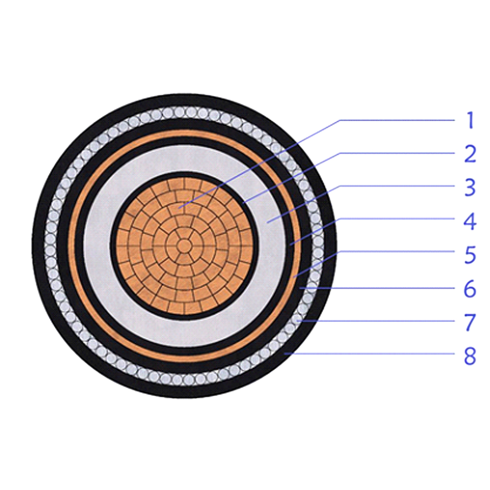
This 8.7/15(17.5)kV medium voltage power cable is designed with compacted copper......
+ VIEW MORE
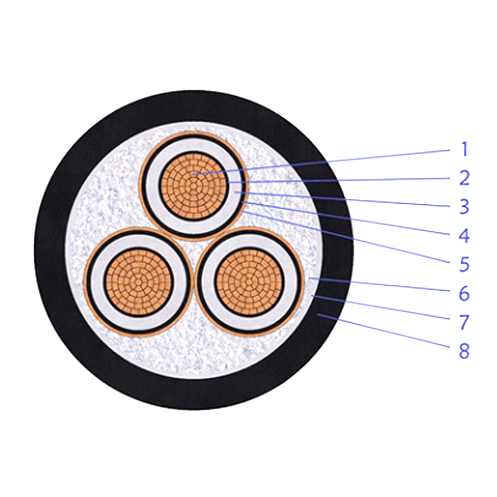
This multi-core XLPE insulated unarmored power cable is designed for medium volt......
+ VIEW MORE
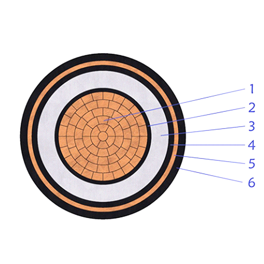
This 8.7/15(17.5)kV XLPE insulated unarmored power cable is developed for medium......
+ VIEW MORE
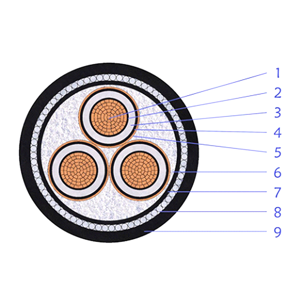
CU/XLPE/CTS/PVC/SWA/PVCThis multi-core medium-voltage power cable features XLPE ......
+ VIEW MORE
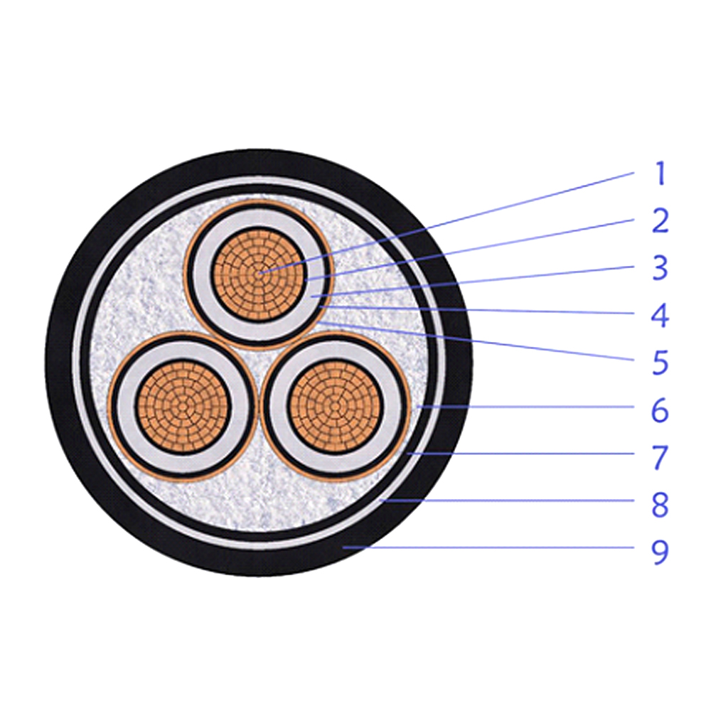
CU/XLPE/CTS/PVC/DSTA/PVCThis multi-core medium-voltage power cable is built with......
+ VIEW MORE
Ready To Customise
Your Cable Products?