Home / News / Industry News / Ground Ampacity Chart: Sizing Equipment Grounding Conductors Correctly
New

Ground Ampacity Chart: Sizing Equipment Grounding Conductors Correctly


What "Ground Ampacity" Actually Refers To

Type "ground ampacity chart" into a search bar and you'll land on two very different kinds of tables, often mixed together on the same page. One shows how much current a conductor can carry continuously before it overheats. The other shows the minimum size a grounding conductor must be, based on the rating of the circuit's overcurrent protective device. They answer different questions, and confusing them leads to conductors that are either oversized for no reason or, worse, undersized for a fault condition.

The first table is the general conductor ampacity chart in NEC Table 310.16, used for any current-carrying wire under normal load. The second is the grounding conductor sizing table in NEC Table 250.122, which applies specifically to equipment grounding conductors (EGCs) — the wires that carry fault current back to the source only when something goes wrong. An EGC isn't sized for continuous load at all; it's sized to safely clear a fault fast enough to trip the breaker or fuse ahead of it. For background on how conductor sizing standards fit together across a project, this guide to LV power cable standards and sizing data covers the broader selection process. NFPA itself publishes a free reference on applying the Article 250 grounding and bonding tables, which is worth bookmarking alongside any chart.

Ground Ampacity Chart: Conductor Sizing by Circuit Rating

Table 250.122 sets the minimum equipment grounding conductor size based on the rating or setting of the overcurrent device protecting the circuit — not on the load current itself. Below is a condensed version covering the ratings most commonly encountered in commercial and light industrial work.

Minimum equipment grounding conductor size by OCPD rating, condensed from NEC Table 250.122.
OCPD Rating (A) Copper (AWG) Aluminum (AWG)
15 14 12
20 12 10
30–60 10 8
100 8 6
200 6 4
300 4 2
400 3 1
600 1 2/0
1000 2/0 4/0
2000 250 kcmil 400 kcmil

Two rules make this table easy to misread if you're moving fast. First, the EGC never needs to be larger than the circuit conductors it's paired with, even if the chart suggests otherwise for an unusually low OCPD rating on an oversized feeder. Second, where circuit conductors are run in parallel across multiple raceways, each raceway still needs an EGC sized off the full OCPD rating — not a fraction of it.

Copper vs Aluminum Grounding Conductors

The chart above shows aluminum consistently one to two sizes larger than copper at the same OCPD rating, which reflects aluminum's lower conductivity per cross-sectional area. That size difference isn't a rounding convenience; it's what keeps the fault-current path low-impedance enough for the breaker to trip promptly.

Copper remains the default choice for EGCs in most commercial and industrial installations because it terminates more reliably and tolerates repeated torque cycles at lugs better than aluminum. Aluminum shows up more often on larger feeders and service entrances, where the weight and cost savings outweigh the extra installation care aluminum terminations require — proper anti-oxidant compound, correctly rated lugs, and periodic torque checks.

Factors That Change the Numbers on the Chart

A chart lookup gives you a starting point, not a final answer. Several conditions push the required size above the table minimum:

  • Motor circuits with high inrush current, sized per 250.122(D) rather than the base table
  • Ground-fault protection settings lower than the OCPD's full rating, which can require a larger EGC than the breaker size alone suggests
  • Increased circuit conductor size for voltage drop — the EGC generally scales up proportionally, per 250.122(B)
  • Cable tray or raceway systems used as the grounding path instead of a discrete wire, which follow separate sizing rules under 392.10

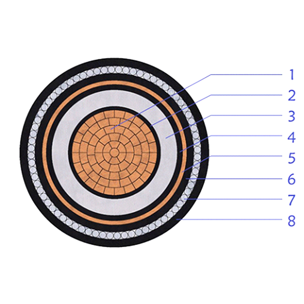
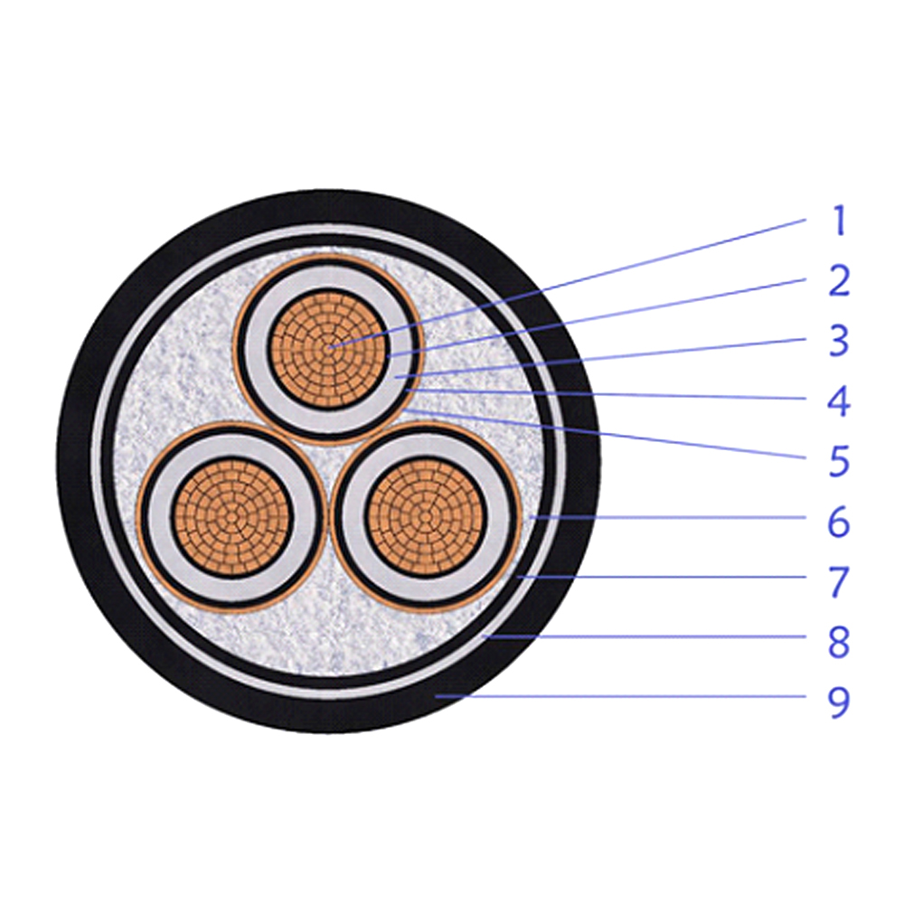
For medium-voltage systems specifically, grounding conductor sizing interacts with insulation level and fault-current withstand ratings in ways the low-voltage table doesn't capture. MV cable sizing, testing, and installation standards is the more relevant reference once a project moves above 1000V.

Choosing the Right Cable for Grounding Applications

Once the chart gives you a target size, the physical cable still has to hold up to the installation environment. Bare or tinned stranded conductors are standard for grounding electrode connections and exposed bonding runs, since there's no fault current flowing under normal conditions and insulation would only add cost without a safety benefit — bare copper and aluminum stranded wire built for these applications is sized to the same AWG references as the chart above.

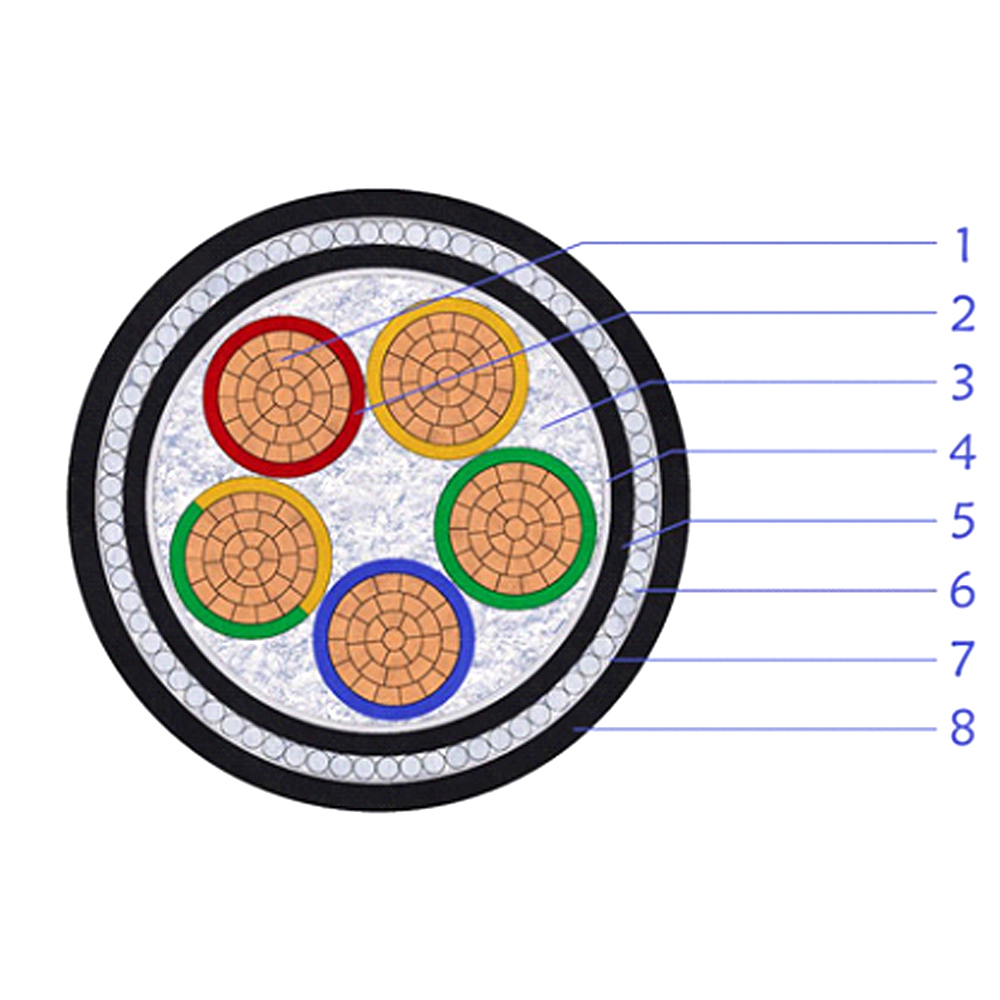
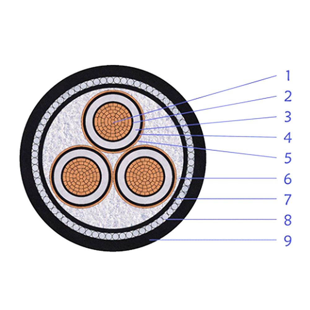
Where the EGC runs alongside power conductors inside a jacketed cable assembly, the surrounding construction matters too. Armored cable designs built for demanding grounding and fault-current conditions add mechanical protection the bare table numbers don't account for, and XLPE insulation construction affects how the conductor handles heat during a sustained fault. On the generation side, grounded PV array systems have their own conductor and bonding requirements — solar cable solutions designed for grounded array installations are built with those field conditions in mind.