+852-68552081


 Language

 English
 русский
 Español
 عربى

Home / News / Industry News / The Role of Single-Core XLPE-Insulated Non-Armoured Cables on the Low-Voltage Side of New-Energy Power Stations
New

Content
Low-voltage distribution cables deployed in new-energy power stations are subject to different requirements from those used in factory buildings and office complexes. The output of photovoltaic arrays rises as the sun climbs, stays near peak values for several hours around noon, and then declines. The output of wind-turbine converters varies with real-time wind conditions. These fluctuating currents flow from inverters through low-voltage busbars and step-up transformers, before being distributed to auxiliary station loads. All these processes rely on cables selected at the design stage, which remain in service for decades afterwards.
A widely adopted solution is the 0.6/1 kV single-core cable with copper conductors, cross-linked polyethylene (XLPE) insulation and polyvinyl chloride (PVC) sheath. It features annealed copper conductors, cross-linked polyethylene insulation, and a polyvinyl chloride outer sheath, with no metallic armour between the insulation and sheath. This article describes the circuit sections within new-energy facilities where this cable type is applied, explains why omitting armour represents sound engineering practice rather than a pure cost-saving measure, and identifies ampacity and installation conditions that govern its expected performance.
Photovoltaic power stations require separate cables for direct-current (DC) and alternating-current (AC) sides. String circuits running from modules to combiner boxes and from combiner boxes to inverters operate at a DC working voltage of 1500 V. These circuits employ photovoltaic-specific cables designed and tested in accordance with EN 50618 or IEC 62930. The 0.6/1 kV cable discussed in this document is installed downstream of inverters: for AC collection and distribution circuits, within low-voltage compartments of box-type substations, and in auxiliary and station-service circuits that supply protective devices, cooling equipment, communication hardware and tracker-mount drive units.
Wind-power facilities follow comparable logic. This voltage class covers auxiliary power supply for tower bases and nacelles, low-voltage output from converters, yaw and de-icing systems, and buildings at wind-farm step-up substations. It also applies to segments inside energy-storage containers, between power-conversion equipment and internal distribution panels. Common characteristics of these applications include load fluctuations driven by natural-resource conditions instead of operational sequences, installation spaces constrained by civil-works or other disciplines, and limited access for maintenance.
This cable has a straightforward configuration. Its performance depends largely on three material selections: conductor copper grade, insulation compound and sheath compound.
|
Component |
Material and Specification |
Function |
|
Conductor |
Annealed copper, Class 2 stranded round or compacted round, complying with IEC 60228 |
Carries load current; stranded construction enables bending and pulling without conductor damage |
|
Insulation |
Cross-linked polyethylene (XLPE) compound |
Sustains a long-term conductor temperature of 90 °C with low dielectric losses |
|
Outer Sheath |
Polyvinyl chloride (PVC/ST2) compound |
Provides mechanical and moisture protection; enables circuit identification through colour-coding |
Conductors use Class 2 stranded annealed copper per IEC 60228, available in round or compacted-round forms. Stranding allows cables to be routed around bends and positioned without the rigidity of solid conductors. Compaction reduces overall outer diameter for a given cross-sectional area, a critical factor for fit-to-install in confined spaces such as conduits and distribution cabinets. Annealed copper is selected for its electrical conductivity and stable behaviour under compression at crimped terminals.
XLPE is a thermosetting insulation material. Cross-linking takes place during manufacturing. Unlike thermoplastic materials, it does not soften and flow under elevated conductor temperatures. This property underpins its 90 °C long-term temperature rating and 250 °C short-circuit temperature rating, and allows XLPE cables of equal copper cross-section to carry higher currents than PVC-insulated alternatives. A trade-off is higher insulation hardness, which demands careful workmanship during stripping and termination.
The PVC/ST2 sheath delivers mechanical and moisture protection not offered by the insulation itself. It withstands typical on-site environmental conditions at power stations and supports circuit identification via colour coding. Its flame-retardant properties satisfy the single-cable vertical flame-spread test defined in IEC 60332-1. Precise wording is important here: compliance with this test restricts flame propagation under specified laboratory conditions and does not confer fire-resistance. Circuits requiring operational integrity during fire exposure need separate cable types qualified by dedicated fire-resistance testing.
Single-core design seldom serves cost objectives; it responds instead to spatial constraints and current-carrying requirements. By concentrating all copper within one conductor, single-core cables achieve improved heat dissipation and higher ampacity compared with multi-core cables of equivalent design. They exhibit smaller outer diameters, allow tighter absolute bending radii, and require only one cable lug for termination, eliminating the need to fit multiple cores inside a single clamping component. These attributes frequently shape layout solutions on transformer platforms, inside containers and within distribution rooms with fixed civil-work dimensions.
Omitting armour involves separate considerations worthy of detailed explanation. Alternating-current circuits generate alternating magnetic fields around each conductor. When such magnetic fields penetrate ferromagnetic materials such as steel wires or steel tapes applied over a single conductor, the armour acts as a short-circuited secondary winding. Eddy-current and hysteresis losses arise, causing armour heating and reducing safe cable ampacity. For this reason, single-core AC cables are either non-armoured or fitted with non-magnetic aluminium-wire armour. Direct substitution with steel-wire-armoured single-core cables requires additional engineering calculations.
Non-armoured construction avoids these magnetic-loss issues and brings further practical benefits: lower mass per unit length, smaller reel dimensions for equal cable lengths, and simplified terminations with no requirement for armour earthing connections. Mechanical protection inherent to the cable is sacrificed, and this trade-off requires deliberate design judgement. Where cable routes pass through crushed-rock backfill, face risks of future excavation, or lie near mobile machinery, risk mitigation relies on alternative installation measures rather than accepting exposure. Suitable options include conduit installation, protective cover plates or installation within enclosed cable trays. If mechanical protection must be integrated into the cable itself, the aluminium-wire-armoured variant of the same cable structure adds a metallic layer while keeping magnetic losses within acceptable limits.
It is not recommended. Module-level and string-level circuits operate at a DC working voltage of 1500 V and demand photovoltaic-specific cables designed and tested to EN 50618 or IEC 62930. The 0.6/1 kV AC-rated cable described in this article does not cover such operating conditions. Cables sized under AC criteria may show insufficient DC withstand performance and ageing resistance.
Direct burial is permissible subject to properly prepared routes and risk assessment. Key influencing parameters include trench-base bedding quality, backfill properties, burial depth and warning tape. Conduit installation or armoured-cable selection represents a more robust approach where mechanical disturbance risks exist. Such assessments should occur during the design phase rather than through on-site modifications.
This configuration is acceptable and common for this voltage class. The three cables shall be laid along the same route. Trefoil formation is preferred where practical. Derating factors for grouped installation shall follow applicable standards, and earthing and bonding of adjacent metallic enclosures shall be engineered accordingly.
It does not. The sheath meets IEC 60332-1 requirements for flame spread on single cables, which only limits flame propagation under defined test conditions. Fire-resistance refers to retention of circuit functionality for a specified duration during fire events, and calls for cables validated by dedicated fire-resistance testing.
Once technical specifications are finalised, project schedules depend on consistent supply matching those requirements. The single-core XLPE-insulated non-armoured cable described in this paper is manufactured by Wuxi Xinyu Cable Co., Ltd. Established in 1996 in Yixing, Jiangsu Province, the facility occupies over 160 000 square metres. Its product portfolio covers more than 500 variants, ranging from low-voltage and medium-voltage power cables up to 35 kV, to building wires, overhead insulated cables, control cables and photovoltaic cables. Most cable sizes needed for low-voltage systems in a power-station project can be sourced from one manufacturer, removing the need for order coordination across multiple suppliers for different cross-sections.
Delays for overseas projects often stem from documentation and coordination rather than product performance. Technical specifications are cross-checked against project requirements before production commences. Ampacity calculations state the installation assumptions applied. Routine test reports and data sheets for each cable reel are provided with deliveries. Clarifying these items in advance reduces complications compared with retrospective documentation after goods arrive on-site.
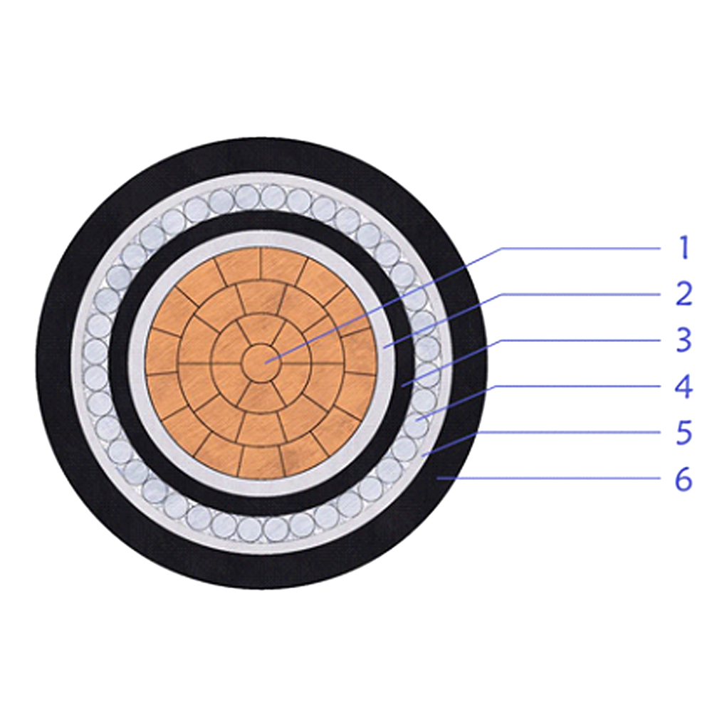
This cable is used as a main power feeder in low-voltage distribution networks. ......
+ VIEW MORE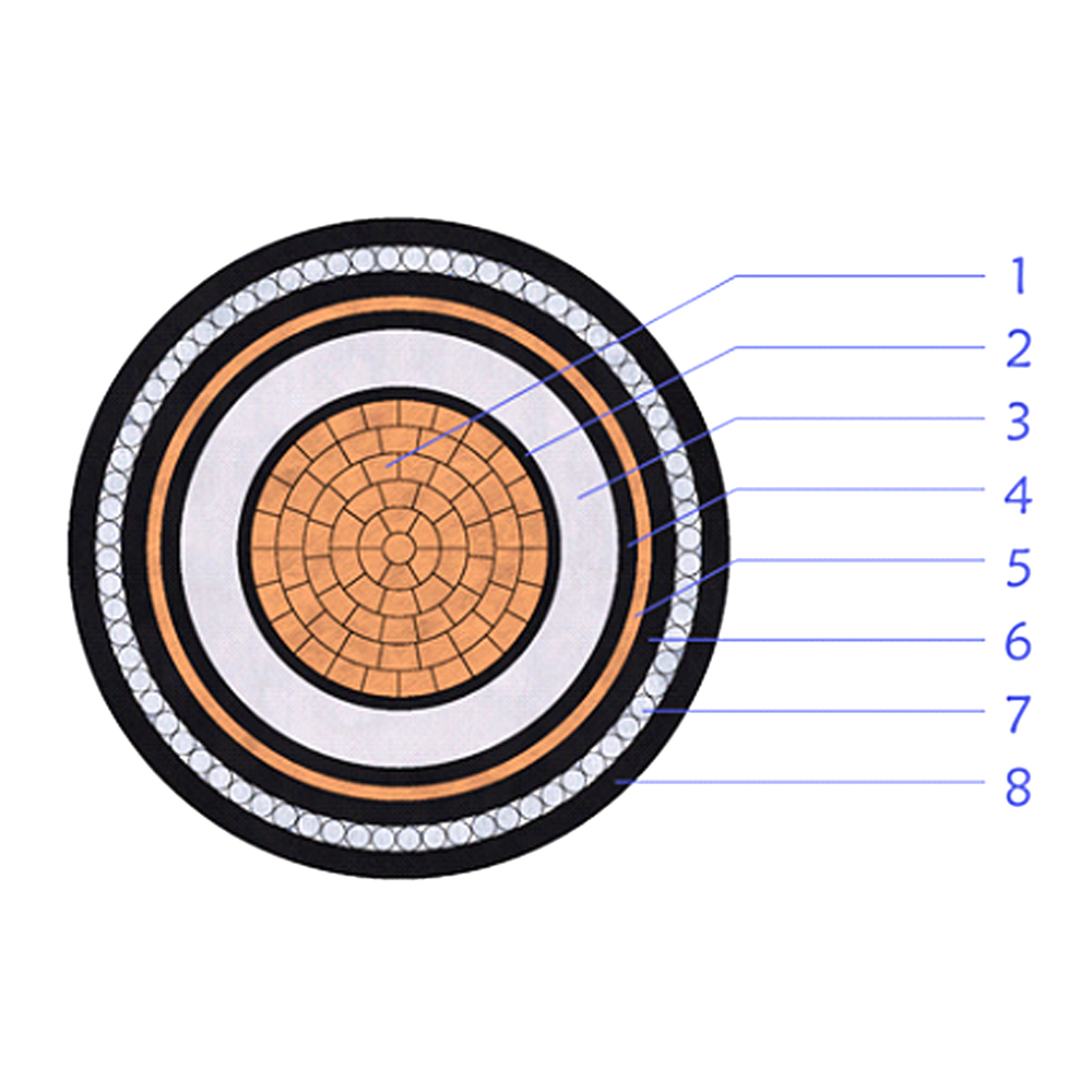
This 3.6/6(7.2)kV medium voltage power cable is designed with a copper conductor......
+ VIEW MORE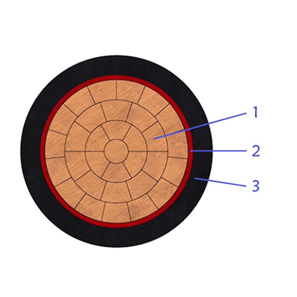
This single-core CU/PVC/PVC cable is designed for low-voltage power transmission......
+ VIEW MORE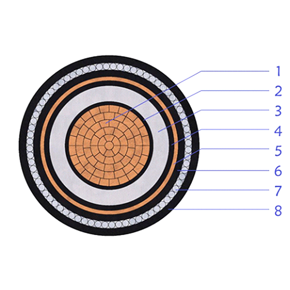
This 8.7/15(17.5)kV medium voltage power cable is designed with compacted copper......
+ VIEW MORE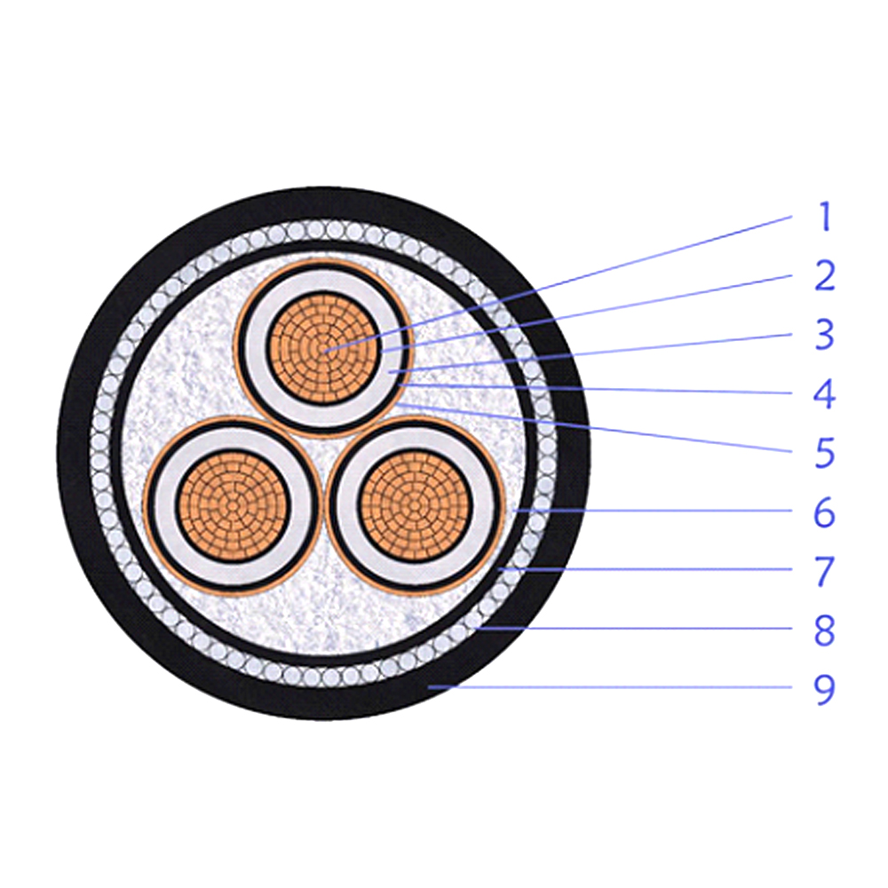
CU/XLPE/CTS/PVC/SWA/PVCThis multi-core medium-voltage power cable features XLPE ......
+ VIEW MORE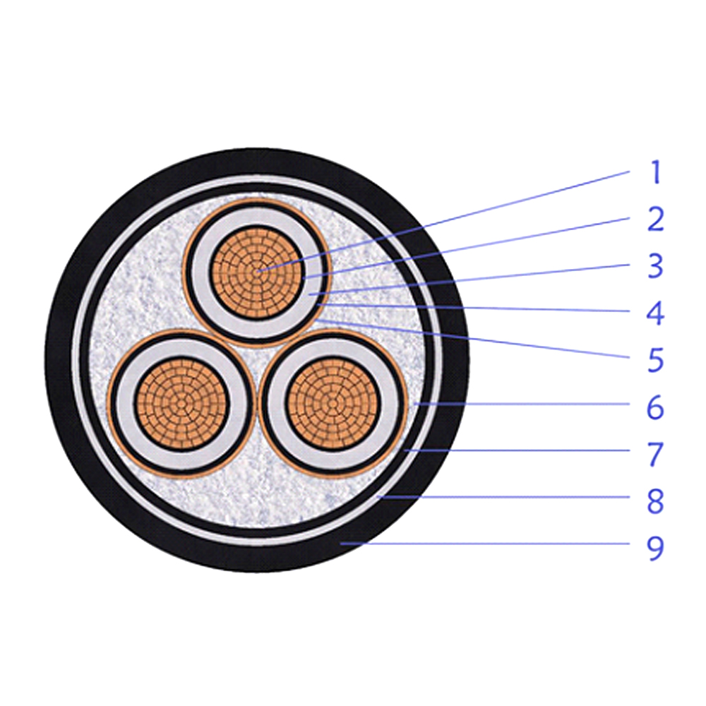
CU/XLPE/CTS/PVC/DSTA/PVCThis multi-core medium-voltage power cable is built with......
+ VIEW MORE
Ready To Customise
Your Cable Products?