+852-68552081


 Language

 English
 русский
 Español
 عربى

Home / News / Industry News / 6 AWG in MM: Diameter, Cross-Sectional Area, and Metric Cable Equivalents
New

Content
A drawing arrives marked "6 AWG copper." The supplier's quotation comes back in square millimetres. Between those two documents sits a conversion that is simple to perform and surprisingly easy to get wrong - and the penalty shows up later as an undersized feeder, a lug that will not crimp, or a load calculation that fails review.
The short answer: 6 AWG equals 4.115 mm in conductor diameter and 13.3 mm² in cross-sectional area. The diameter is an exact conversion from inches. The area is the geometric area of the metal, and it is not a standard metric cable size - which is why buyers in metric markets are almost always asked to choose between 10 mm² and 16 mm² as the substitute.
The sections below cover where those numbers come from, how they behave on stranded conductors, and how to pick a metric equivalent without giving away current-carrying capacity.
American Wire Gauge is an inch-based system, so every gauge has an exact metric equivalent. For 6 AWG the working values are a nominal diameter of 4.115 mm (0.1620 in), a cross-sectional area of 13.3 mm², and about 26,250 circular mils.
| AWG | Diameter (mm) | Diameter (in) | Area (mm²) |
|---|---|---|---|
| 4 | 5.189 | 0.2043 | 21.2 |
| 5 | 4.621 | 0.1819 | 16.8 |
| 6 | 4.115 | 0.1620 | 13.3 |
| 7 | 3.665 | 0.1443 | 10.5 |
| 8 | 3.264 | 0.1285 | 8.37 |
Two of those values are routinely confused. The 4.115 mm is the diameter of a solid round conductor, while 13.3 mm² is the area of the metal. When a specification says only "6 AWG," both numbers sit behind that designation, and it pays to know which one the other party actually needs.
AWG diameters follow a geometric progression: d = 0.005 in × 92^((36 − n)/39), where n is the gauge number. For n = 6 the exponent is 30/39, the step factor works out to roughly 32.4, and the result is 0.1620 in. Multiply by 25.4 and you get 4.1148 mm, normally written as 4.115 mm.
Because the definition is anchored in inches and the inch is exactly 25.4 mm, the conversion itself introduces no approximation. When two online converters disagree - 4.115 mm against 4.1148 mm - that is a rounding choice, not a different answer. On a cable drawing, the gap is far below any practical tolerance.
On a solid 6 AWG conductor, a caliper across the copper should read close to 4.115 mm. On a seven-strand 6 AWG conductor, each strand is about 1.55 mm across and the bundle measures roughly 4.6 to 4.7 mm, even though the metal area is identical. This is the most common reason a technician believes a shipment is out of specification when it is perfectly normal.
AWG dimensions are published as nominal values. Standards set the nominal diameter for each gauge and, separately, the tolerances that apply to finished cable, insulation thickness, and electrical performance. If you need an inspection criterion, work from the applicable conductor standard rather than comparing a caliper reading against 4.115 mm. For any electrical calculation, the number that matters is the area - 13.3 mm² - because resistance, ampacity, and voltage drop all follow from it.
Metric cable is manufactured in fixed steps: 1.5, 2.5, 4, 6, 10, 16, 25 mm², and so on. Since 13.3 mm² is not one of them, a 6 AWG conductor is normally replaced by 10 mm² (close to 8 AWG) or by 16 mm² (close to 5 AWG). Both substitutions can be right, but not for the same reason.
For orientation, IEC-style installation tables commonly place a 10 mm² PVC-insulated copper conductor in the low 50 A range under typical fixing methods, while 16 mm² reaches roughly 70 A. The exact figure depends on insulation material, the number of loaded conductors, ambient temperature, and installation method. Our LV power cables cover this size range, which makes side-by-side substitution straightforward when a design moves between AWG and metric sizing.
A diameter conversion tells you whether a lug will fit. It does not tell you whether the circuit will work. That answer comes from ampacity and resistance, and 6 AWG has well-established values for both.
| Insulation temperature rating | Copper, 6 AWG | Aluminum, 6 AWG |
|---|---|---|
| 60 °C | 55 A | 40 A |
| 75 °C | 65 A | 50 A |
| 90 °C | 75 A | 55 A |
On resistance, 6 AWG copper measures about 1.61 Ω per km at 20 °C (0.491 Ω per 1,000 ft), and 6 AWG aluminum about 2.65 Ω per km. Resistance climbs with temperature - roughly 20% higher at 75 °C than at 20 °C for copper - so voltage-drop work done with room-temperature figures is slightly optimistic.
As a worked example, a 50 m run of 6 AWG copper carrying 60 A on a 240 V single-phase circuit loses about 9.7 V over the round trip, close to 4% of supply voltage, and a little more once the conductor reaches operating temperature. Push the same load to 80 m and stepping up to a 16 mm² conductor turns from a technicality into an economic decision. Our published LV power cable selection guide follows the same sizing logic with worked examples.
The gauge turns up in a fairly consistent set of applications:
When these projects are built to metric documentation, the substitution above is routine. For 450/750 V building wiring, a PVC-insulated conductor in 10 or 16 mm² lands in the same terminals as 6 AWG in most panel work:
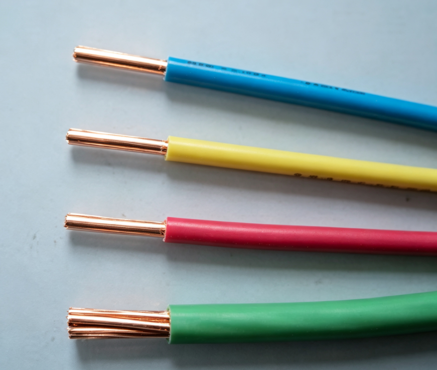 PVC-Insulated 450/750 V Building Wire for Fixed WiringCost-effective PVC-insulated copper cable for 450/750 V fixed power and lighting wiring, suitable for metric building-wiring substitutions in panel work.View Product →
On the DC side of a solar array, the conductor also has to survive UV exposure, ozone, and wide temperature swings, which is a different requirement from ampacity alone:
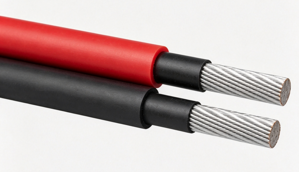 Photovoltaic DC Cables for Solar Module and Combiner ConnectionsSingle-core flexible PV cables with tinned copper and XLPO insulation for outdoor solar DC connections subject to UV, ozone, and temperature swings.View Product →
The conversion is the easy part. The ordering paperwork is where the expensive mistakes happen, so a few points belong on your checklist.
Where a metric equivalent will sit permanently in feeder and distribution work, XLPE insulation provides more thermal headroom at the same cross-section:
 CU/XLPE/PVC 0.6/1 kV Single-Core Unarmored Power CableXLPE-insulated copper cable for fixed feeder and distribution work, worth checking when a metric equivalent must carry the required ampacity.View Product →
6 AWG is 4.115 mm across and 13.3 mm² in area, and those two facts solve different problems: one fits the lug, the other carries the current. When a drawing has to be built in metric cable, 16 mm² is the safe substitution for ampacity, while 10 mm² works only where the load allows it. Confirm the standard, the stranding class, and the temperature rating before the order leaves the desk, and the conversion stops being a source of risk.
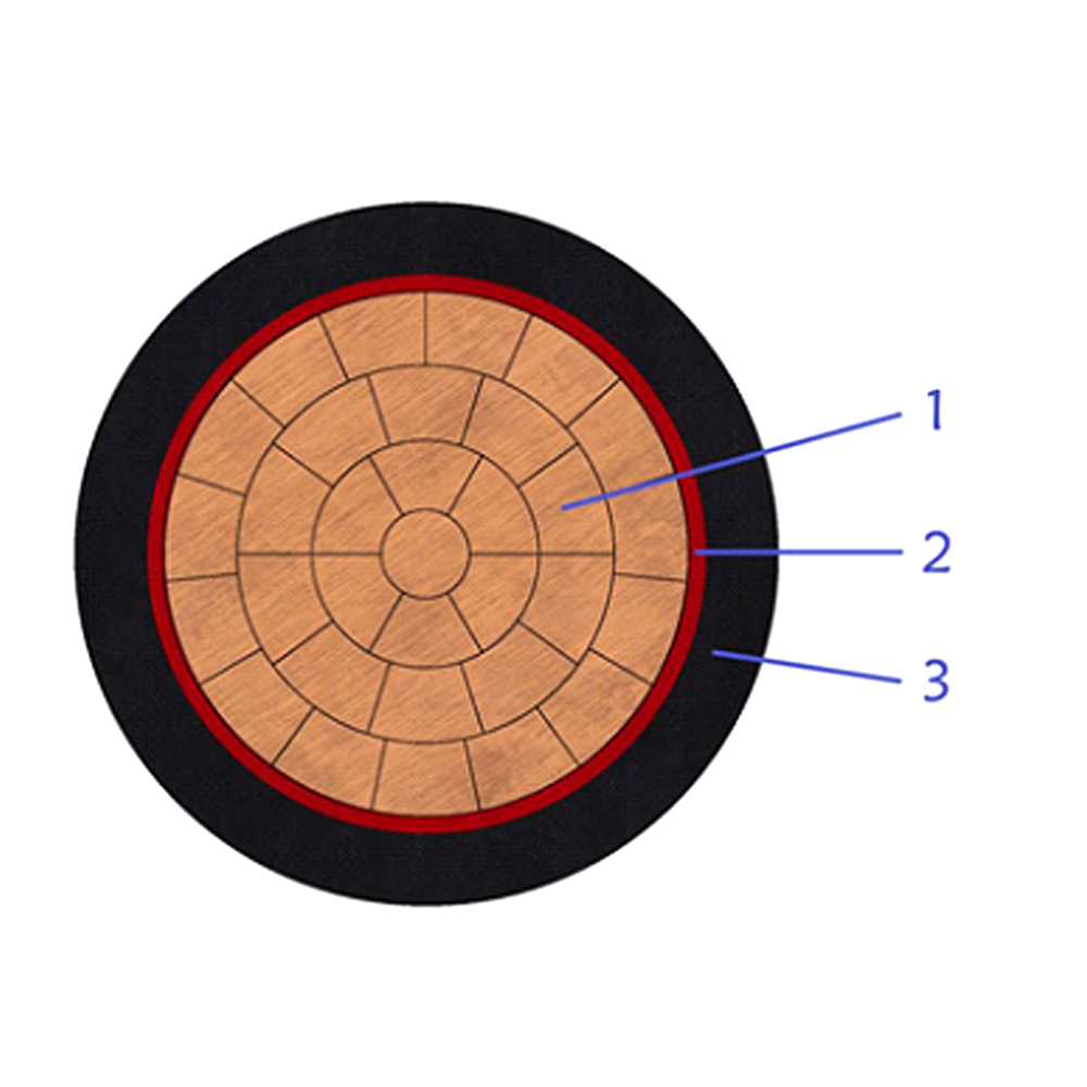
This single-core CU/PVC/PVC cable is designed for low-voltage power transmission......
+ VIEW MORE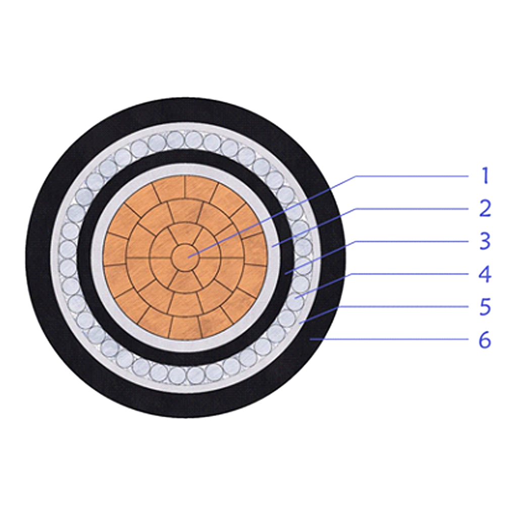
This cable is used as a main power feeder in low-voltage distribution networks. ......
+ VIEW MORE
This single-core XLPE insulated PVC sheathed cable is ideal for low-voltage powe......
+ VIEW MORE
This 3.6/6(7.2)kV medium voltage power cable is designed with a copper conductor......
+ VIEW MORE
This 6/10(12)kV medium voltage power cable is manufactured with copper conductor......
+ VIEW MORE
This 6/10(12)kV XLPE insulated unarmored power cable is intended for medium volt......
+ VIEW MORE
Ready To Customise
Your Cable Products?