+852-68552081


 Language

 English
 русский
 Español
 عربى

Home / News / Industry News / 15 Gauge Wire in mm: AWG vs SWG Diameter, Area, and Metric Equivalents
New

Content
A maintenance engineer forwards a drawing that specifies "15 gauge" wire and asks for the metric equivalent. There are two defensible answers, 1.45 mm and 1.83 mm, and the gap between them is not a rounding detail. One is an American Wire Gauge size with roughly 1.65 mm² of copper; the other is a Standard Wire Gauge size with about 2.63 mm². Choosing the wrong one changes the conductor cross-section by nearly 60%, which surfaces later as unexpected voltage drop, a terminal that will not accept the wire, or a bending radius that no longer fits the duct.
If the drawing, catalogue page or legacy specification is North American, 15 gauge almost certainly means AWG 15: 0.0571 inch, or 1.45 mm in diameter, with a nominal cross-section of 1.65 mm². If it originates from older British, Indian or Commonwealth documentation, it more likely means SWG 15: 0.072 inch, or 1.83 mm, with 2.63 mm² of copper. B&S gauge, which appears on some alloy wire datasheets, is the same table as AWG, so B&S 15 and AWG 15 are identical.
The table below places both readings next to the sizes engineers usually substitute for them. Resistance values are calculated from nominal area for plain annealed copper at 20 °C; published limits for finished cable run slightly higher.
| Gauge reference | Diameter (in) | Diameter (mm) | Nominal area (mm²) | Copper resistance (Ω/km, 20 °C) |
|---|---|---|---|---|
| AWG 16 / B&S 16 | 0.0508 | 1.29 | 1.31 | 13.2 |
| AWG 15 / B&S 15 | 0.0571 | 1.45 | 1.65 | 10.4 |
| AWG 14 / B&S 14 | 0.0641 | 1.63 | 2.08 | 8.28 |
| SWG 15 | 0.0720 | 1.83 | 2.63 | 6.56 |
| 1.5 mm² (IEC class 2) | n/a | 1.38 solid | 1.5 | 12.1 max |
| 2.5 mm² (IEC class 2) | n/a | 1.78 solid | 2.5 | 7.41 max |
One coincidence is worth remembering: SWG 15 is dimensionally identical to AWG 13. The two systems drift apart by roughly two numbers, so a document that mixes them can be off by two wire sizes without anyone noticing.
AWG was fixed in 1857 by the Brown & Sharpe company and later became the American standard for round conductors. Its progression is logarithmic: every three gauge steps doubles the area, which is why the numbers fall as the wire grows thicker. SWG was legalised in Britain in 1884 for the same purpose but follows a different progression, and it survived in legacy plant drawings, transformer leads and imported machinery long after metrication.
Neither table is wrong, and neither is more metric than the other. The practical rule is to treat a gauge number as incomplete until the standard is named. A useful habit is to convert to millimetres or square millimetres straight away and write the result on the drawing, because a bare "15 GA" note will be read differently by whoever picks up the file next.
Diameter alone understates the difference. Conductor capacity scales with area, and AWG 15 at 1.65 mm² carries about 10% more copper than a 1.5 mm² IEC conductor and about 34% less than 2.5 mm². Its calculated resistance of roughly 10.4 Ω/km sits between the IEC 60228 limits of 12.1 Ω/km for 1.5 mm² class 2 and 7.41 Ω/km for 2.5 mm² class 2. That resistance figure is what matters for voltage drop, loop impedance and fault-current calculations; the millimetre figure only tells you whether the wire physically fits.
For 450/750 V panel, appliance and building wiring, the closest catalogue family in a metric plant is PVC-insulated single-core wire, where 1.5 mm² is the standard stock size and AWG 15 is effectively a custom item.
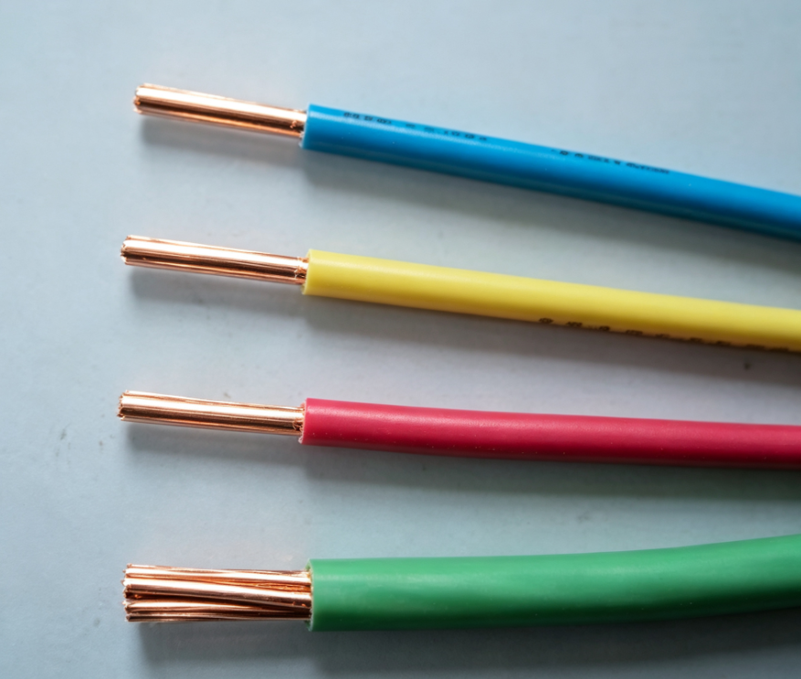 PVC-Insulated Single-Core Wire for 450/750 V WiringA metric stock 1.5 mm² alternative for panel, appliance and building wiring when AWG 15 requires substitution; check resistance and termination hardware.View Product →
Because AWG 15 is not a stock size in most metric catalogues, substitution is usually unavoidable. The decision should be driven by the resistance budget and the termination hardware rather than by appearance.
| Option | Approximate diameter (mm) | Nominal area (mm²) | Resistance versus AWG 15 | Typical reason to choose it |
|---|---|---|---|---|
| 1.5 mm² IEC | 1.38 solid | 1.5 | +16% | Shelf stock, panel and building wiring |
| AWG 15 | 1.45 | 1.65 | baseline | Legacy drawing, OEM specification |
| AWG 14 | 1.63 | 2.08 | −21% | Standard North American size |
| 2.5 mm² IEC | 1.78 solid | 2.5 | −29% | Long runs, higher current, voltage drop margin |
A worked example makes the trade-off concrete. Take a 10 A load at the end of a 30 m single-phase run. With AWG 15 the conductor drop is about 6.2 V; with 1.5 mm² it rises to roughly 7.3 V; with 2.5 mm² it falls to about 4.4 V. If the circuit already sits close to a 5% drop limit, that one-volt difference decides whether the design passes. Stepping up to 2.5 mm² solves the electrical problem but may not fit a terminal block, connector cavity or wiring duct sized around a 1.45 mm conductor, so check termination capacity before finalising. The same reasoning applied to larger conductors is covered in this guide to low voltage power cable sizing and standards.
Two cables with identical 1.65 mm² conductors can carry very different currents. A PVC-insulated conductor is limited to a 70 °C conductor temperature, an XLPE-insulated one to 90 °C, and both are further derated for ambient temperature, grouping, enclosure, thermal insulation and installation method. Free-air chassis tables often list 15 AWG copper at roughly 5 to 7 A, while installation tables for a similar conductor area quote higher figures under favourable conditions. The numbers differ because the underlying assumptions differ, not because the copper does.
For equipment with several conductors bundled together, apply the grouping factor before comparing against a supplier's headline rating, and confirm whether that rating assumes free air, conduit or tray. The logic is identical for low voltage power cables and for small control conductors.
AWG and SWG numbers describe a conductor's nominal area, not its outline. A solid 15 AWG copper wire measures 1.45 mm across; a 19-strand version of the same nominal area measures noticeably more overall because of the gaps between strands, and a fine-strand flexible version more again. IEC 60228 classes 1, 2, 5 and 6 formalise this distinction, and it is why flexible cords are specified by class rather than by gauge alone.
Two checks remove most of the ambiguity from a purchase order: state the standard (AWG, SWG or mm²) and specify a maximum conductor resistance instead of a diameter tolerance. A resistance acceptance covers stranding, tinning and copper quality in one measurement, whereas a diameter check can pass a wire that is dimensionally correct but electrically short.
 Plastic-Insulated Control Cable for Signal and Interlock CircuitsFor control cabinets, instruments and actuators up to 450/750 V; useful when specifying signal cable by resistance and standard rather than gauge alone.View Product →
North American distributors stock 14 and 16 AWG; metric suppliers stock 1.5 and 2.5 mm². A 15 AWG request therefore lands between two standard production runs, and the answer depends on order quantity, insulation compound and whether the conductor must be tinned or bare. For small quantities, expect either a substitution proposal or a minimum-order requirement. For repeat OEM volumes a dedicated run is normally straightforward, because the drawing sits only slightly off the standard 1.5 mm² line.
Signal and instrumentation circuits follow the same conversation, except that shielding, pair geometry and capacitance matter more than the gauge number itself.
 Computer and Instrumentation Cable for Analogue and Digital SignalsTwisted-pair, optionally shielded construction for DCS, PLC and instrument links up to 300/500 V; review capacitance and shielding when gauge is secondary.View Product →
When requesting quotes, send the standard, the required resistance or current, the insulation and sheath material, the temperature rating, the core count and any environmental approvals. That set of parameters can be priced accurately; a note reading "15 gauge wire" cannot.
Fifteen gauge is a small illustration of a wider habit: one number travels between two measurement traditions and quietly changes meaning along the way. Converting it to 1.45 mm for AWG or 1.83 mm for SWG settles the diameter question in seconds. What protects the project afterwards is carrying that conversion through to area, resistance and the physical space the conductor has to occupy.
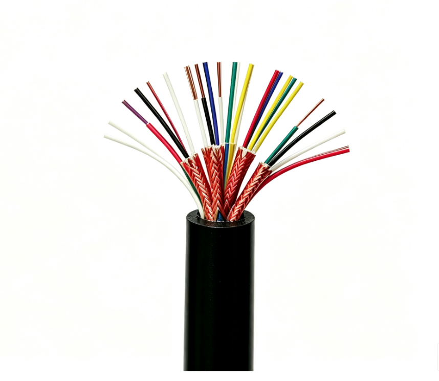
Xinyu Flame-Retardant Computer and Instrumentation Cables are designed for the t......
+ VIEW MORE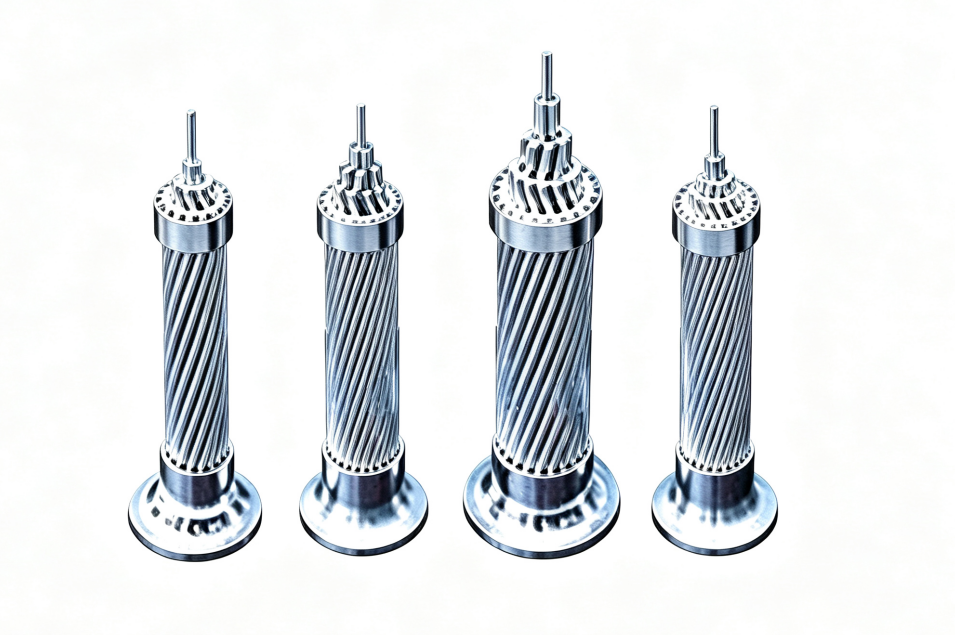
As bare conductive products, aluminum stranded wires are suitable for low-voltag......
+ VIEW MORE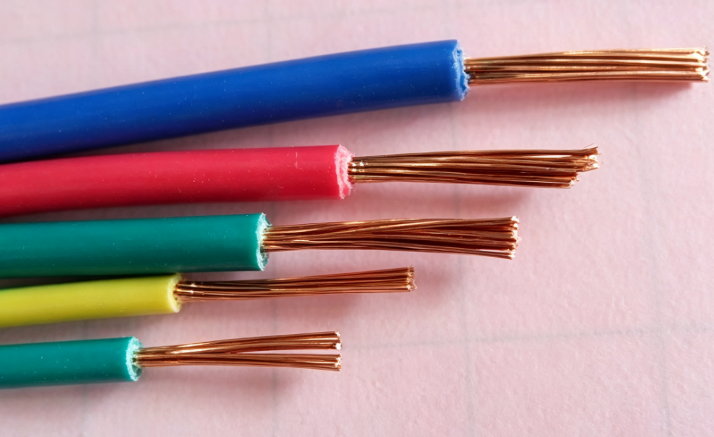
Suitable for fixed wiring, power and lighting circuits, internal and external co......
+ VIEW MORE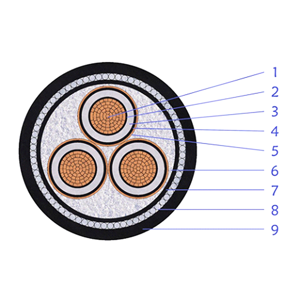
This 8.7/15kV multi-core power cable adopts a layered design based on compacted ......
+ VIEW MORE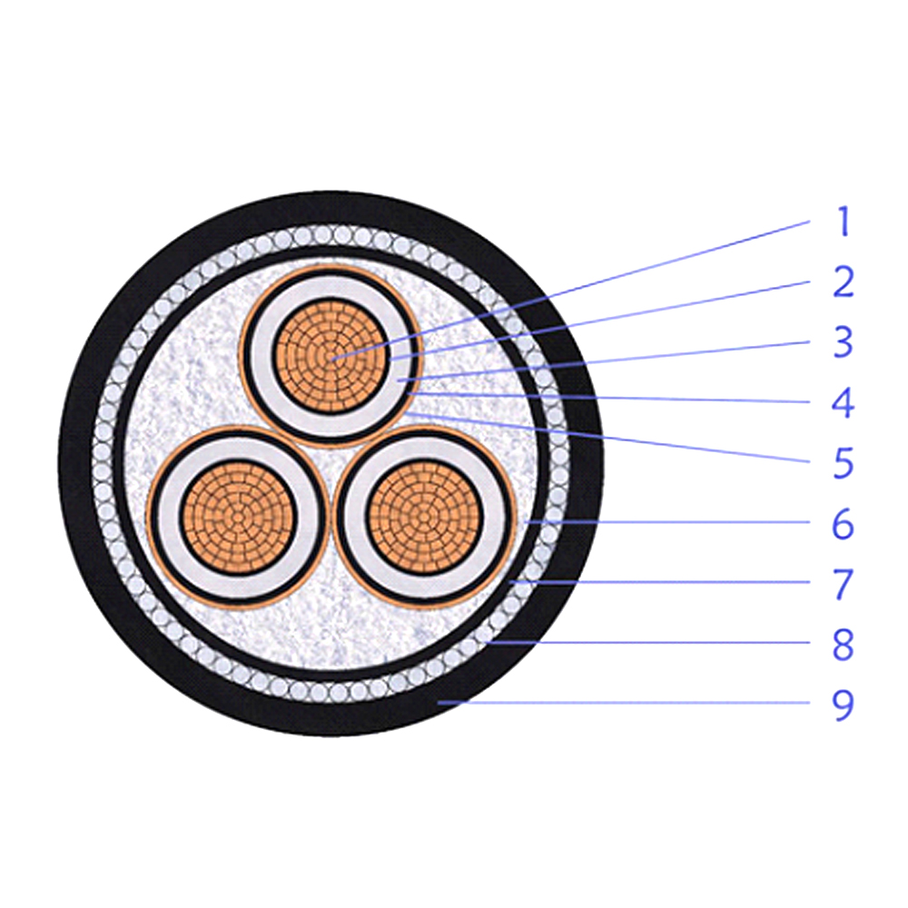
This medium voltage power cable is designed with multi-core copper conductors in......
+ VIEW MORE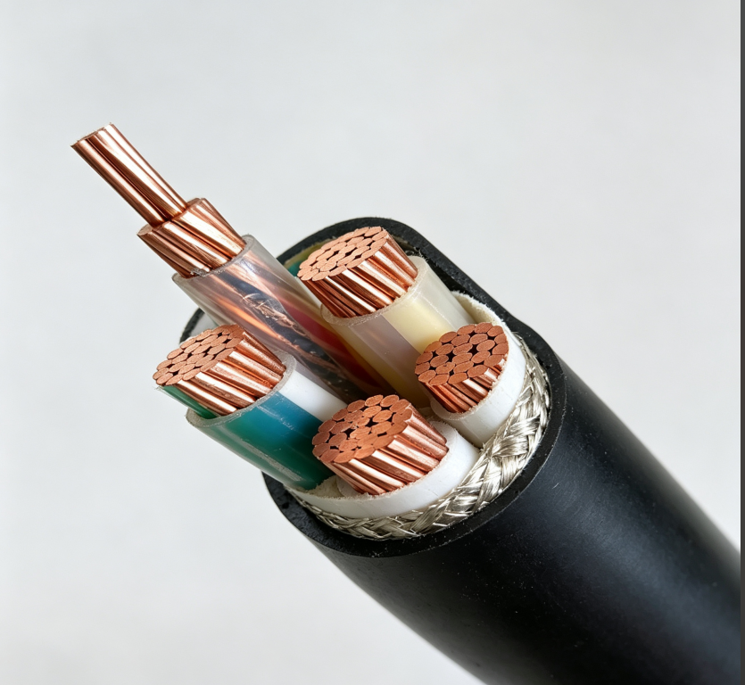
Suitable for transmission of control, interlock and measuring signals in seconda......
+ VIEW MORE
Ready To Customise
Your Cable Products?